


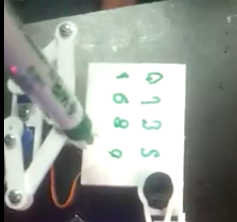
サーボはプログラムで指定した位置に動作していますか?不明であれば、描かれた画像または動画をアップしてはいかがでしょうか?
###前提・実現したいこと
rduinoとサーボモータ(SG90)3つを使って、数字を描くロボットアームを作っています。PlotClockというデジタル時計を実現したプロトタイプが存在し、以下がその参考にしているサイトです。ハードウェアはThingiverseからそのまま3Dプリンタで印刷しました。
###発生している問題・エラーメッセージ
数字の「1」と「2」を描くためのコードをgithubの参考コードから抜粋し、サーボは動きます。しかしながら、その動きが、「1」も「2」も同じで数字が判別できない状態に陥っています。「3」や「6」もうまくかけていない状態で、困っています。
異なる数字のコードをArduinoに書き込んでも、この動画にあるような動きがひたすら続きます。
数字の「1」を描くためのコード
「1」を描く部分は参考コードの189,190行目から抜粋しました。
###該当のソースコード
Arduino
1// delete or mark the next line as comment when done with calibration 2#define CALIBRATION 3 4// When in calibration mode, adjust the following factor until the servos move exactly 90 degrees 5#define SERVOFAKTORLEFT 650 6#define SERVOFAKTORRIGHT 650 7 8 9// Zero-position of left and right servo 10// When in calibration mode, adjust the NULL-values so that the servo arms are at all times parallel 11// either to the X or Y axis 12#define SERVOLEFTNULL 1900 13#define SERVORIGHTNULL 984 14 15#define SERVOPINLEFT 3 16#define SERVOPINRIGHT 4 17 18// length of arms 19#define L1 35 20#define L2 55.1 21#define L3 13.2 22 23// origin points of left and right servo 24#define O1X 22 25#define O1Y -25 26#define O2X 47 27#define O2Y -25 28 29#include <Servo.h> 30 31Servo servo1; // 32Servo servo2; // 33Servo servo3; // 34 35volatile double lastX = 75; 36volatile double lastY = 47.5; 37 38 39void setup() { 40 // put your setup code here, to run once: 41 drawTo(75.2, 47); 42 43 servo2.attach(SERVOPINLEFT); // left servo 44 servo3.attach(SERVOPINRIGHT); // right servo 45 delay(1000); 46} 47 48void bogenGZS(float bx, float by, float radius, int start, int ende, float sqee) { 49 float inkr = 0.05; 50 float count = 0; 51 52 do { 53 drawTo(sqee * radius * cos(start + count) + bx, 54 radius * sin(start + count) + by); 55 count += inkr; 56 } 57 while ((start + count) <= ende); 58} 59 60 61void drawTo(double pX, double pY) { 62 double dx, dy, c; 63 int i; 64 65 // dx dy of new point 66 dx = pX - lastX; 67 dy = pY - lastY; 68 //path lenght in mm, times 4 equals 4 steps per mm 69 c = floor(4 * sqrt(dx * dx + dy * dy)); 70 71 if (c < 1) c = 1; 72 73 for (i = 0; i <= c; i++) { 74 // draw line point by point 75 set_XY(lastX + (i * dx / c), lastY + (i * dy / c)); 76 77 } 78 79 lastX = pX; 80 lastY = pY; 81} 82 83void set_XY(double Tx, double Ty) 84{ 85 delay(1); 86 double dx, dy, c, a1, a2, Hx, Hy; 87 88 // calculate triangle between pen, servoLeft and arm joint 89 // cartesian dx/dy 90 dx = Tx - O1X; 91 dy = Ty - O1Y; 92 93 // polar lemgth (c) and angle (a1) 94 c = sqrt(dx * dx + dy * dy); // 95 a1 = atan2(dy, dx); // 96 a2 = return_angle(L1, L2, c); 97 98 servo2.writeMicroseconds(floor(((a2 + a1 - M_PI) * SERVOFAKTORLEFT) + SERVOLEFTNULL)); 99 100 // calculate joinr arm point for triangle of the right servo arm 101 a2 = return_angle(L2, L1, c); 102 Hx = Tx + L3 * cos((a1 - a2 + 0.621) + M_PI); //36,5° 103 Hy = Ty + L3 * sin((a1 - a2 + 0.621) + M_PI); 104 105 // calculate triangle between pen joint, servoRight and arm joint 106 dx = Hx - O2X; 107 dy = Hy - O2Y; 108 109 c = sqrt(dx * dx + dy * dy); 110 a1 = atan2(dy, dx); 111 a2 = return_angle(L1, (L2 - L3), c); 112 113 servo3.writeMicroseconds(floor(((a1 - a2) * SERVOFAKTORRIGHT) + SERVORIGHTNULL)); 114 115} 116 117double return_angle(double a, double b, double c) { 118 // cosine rule for angle between c and a 119 return acos((a * a + c * c - b * b) / (2 * a * c)); 120} 121 122 123void loop() { 124 // put your main code here, to run repeatedly 125 126 // Servohorns will have 90° between movements, parallel to x and y axis 127 drawTo(-3, 29.2); 128 delay(500); 129 drawTo(74.1, 28); 130 delay(500); 131 132} 133 134//1を書く 135void number(float bx, float by, int num, float scale) { 136 137 drawTo(bx + 10 * scale, by + 20 * scale); 138 drawTo(bx + 10 * scale, by + 0 * scale); 139}
数字の「2」を描くためのコード
void loop()までは数字の「1」を描くためのコードと同様
「2」を描く部分は参考コードの196~198行目から抜粋しました。
Arduino
1void number(float bx, float by, int num, float scale) { 2 3 4 bogenUZS(bx + 8 * scale, by + 14 * scale, 6 * scale, 3, -0.8, 1); 5 drawTo(bx + 1 * scale, by + 0 * scale); 6 drawTo(bx + 12 * scale, by + 0 * scale); 7}
###補足情報(言語/FW/ツール等のバージョンなど)
ハードウェアをサーボにつける前にキャリブレーションが必要かもしれないのですが、方法がわからず、キャリブレーションなどはせずにそのままハードウェアを装着しました。
<現状>
1や2を描くためのコードが読み込まれておらず、現状ではキャリブレーションのみを行なっている可能性があると気がつきました。
他の製作者のキャリブレーション様子
動画を追加させていただきました。ご提案ありがとうございます。
追記で失礼します。現状の動きはキャリブレーションのみの可能性があるかもしれません。
回答1件
あなたの回答
tips
プレビュー


